Piro - Blog
Oct 4th, 2015 - Speech recognition noise reduction work
During the past couple of weeks I have not been able to make a lot of progress with Piro. Partly because I have been a bit sick, and partly because both this and previous Saturday I was not able to work on Piro. Saturday is usually my best hobby working day, but this Saturday we had a storm and a blackout that lasted several hours, and the previous Saturday I had a university class reunion. So, I have only been able to work on Piro a couple of hours during the whole two week period.
I have however started working on some noise reduction algorithms to the speech recognition code. First, I added code that records all the audio that Piro hears when it is balancing. I did a couple of balancing runs, and analyzed the resulting audio. Here below is a clip of the background noise Piro hears while balancing. There is some analog hiss from the cheap microphone components, then the motor gear noise when the balancing algorithm rotates the wheels (with a louder click when it switches direction), and a couple of louder segments where Piro turns the head servos. All of these are sounds that I would like to reduce as much as possible.
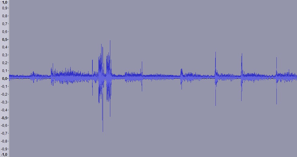
If your browser supports HTML5, you can also hear the actual audio recording (that corresponds to the wave image above) below.
After recording the full audio, I began hunting for examples of audio noise reduction algorithms. I found various mathematical descriptions, and several Matlab algorithms, but sadly I am not sufficiently fluent in mathematics to be able to convert those into C code. Finally I found what I was looking for, the source code for the Audacity Noise Reduction effect. This was a good find, as I have been using Audacity and it's Noise Reduction effect every now and then in the past, so I had a good idea about what it can do.
The Audacity Noise Reduction effect is not directly suitable for real-time on-the-fly noise reduction that I need, so I am currently studying it and figuring out ways to get something similar done in real time. The first step in this work was to be able to convert the speech recognition frame data back from frequence domain to time domain (using Inverse FFT), so that I can debug the noise reduction results. I was able to get this working just a couple of days ago, so now I can continue working on the actual noise reduction features. I expect it to be pretty difficult (if not impossible) to get rid of all the background noise, but it is interesting to see how far I can get.
Sep 20th, 2015 - Balancing adjustments, behavioral code work
We had the company meeting on the 10th of this month, and I was asked to demonstrate my robot as the first event on the agenda for the day. I was a bit worried about everything that might go wrong with it, but luckily Piro decided to behave quite well during the demonstration. :-) I had coded a system where Piro would introduce itself when it detects a face for the first time, and I had also coded a simple command handling system for a couple of spoken commands ("Piro", "Testing", "Turn Left" and "Turn Right"). I let Piro balance on a smallish table (so I had to guard it from falling over the edges) sideways from the audience, and then commanded it to turn towards the audience. I had hoped it would detect the faces at this point, but I had to adjust the head angle a bit until it detected faces in the audience and introduced itself. I then spoke a couple more commands, which resulted in Piro turning away from the audience. After a short balancing run I turned Piro upside down, and it shut itself down nicely, so I could then focus on telling the audience about my work on the robot. I pretty much showed this blog of mine and told about the most noteworthy blog entries. Quite a successful demonstration overall.
After the event I have mostly been working on the balancing routine, trying to make it more robust against the changing center of gravity. This work is still ongoing, as I am still not quite happy with my current code. It is already better than what it was during the demonstration, but it still needs more work. Wheel encoders might be useful for this, but I am trying to get by without them for now. I still have not connected the ultrasonic sensor, but I hope that using it together with the estimated wheel turning speed (and perhaps even the accelerometer readings) I should be able to come up with a way to estimate the robot's position and speed (and thus also adjust the balancing angle) with reasonable accuracy.
This weekend I decided to work on the behavioral routines again. I implemented code to turn the head servos, and coded a system where the face detection algorithm commands the head servos to turn the head towards the detected face. I made some test runs and took a video of one such test run. In the video Piro is also introducing itself, using the same code as I used in the company demonstration. In the future I should also add code that tries to re-acquire a face that was detected in earlier frames but was not detected in the new frames. Currently Piro has no idea where to look for a face that is no longer detected.
Both the wheel motors and the servos cause so much audible noise that the speech recognition accuracy is pretty poor, Piro keeps hearing commands even though I did not say anything during the whole video. I think the next big issue I need to work on is improving the speech recognition. I need to adapt the language model to my voide (and the microphones I use), and then figure out a way to filter out as much of the motor and servo noise as possible. The first step is to record a full balancing run's worth of audio, so that I can properly analyze all the different sounds that Piro hears.
Sep 6th, 2015 - Success at balancing at 10kHz PWM frequency
I spent many days last week troubleshooting and experimenting with the various PWM frequencies. I was not able to make much progress during Monday and Tuesday, and began to get frustrated and annoyed as having the PWM frequency (and thus the audible whine) not in the 200..6000Hz range would be pretty important to be able to use speech recognition in my robot. I was able to get somewhat reasonable balancing at 5kHz frequency, but that noise was even more annoying than the 800Hz whine, and will also cause problems with speech recognition.
Finally on Wednesday I decided to get back to basics. I decided not to try to balance my robot at 10kHz, instead I just ran a simple test code where I could change the PWM duty cycles between zero and maximum, one step at a time using cursor keys, and see (and listen to) how the wheel speed changes. I used the gpioCfgClock command to set the pigpio sample rate to 2 microseconds (500000 Hz), which would give me 50 PWM steps at 10kHz PWM frequency. I then set the L298N controller IN1 input signal to high, and began upping the ENA signal PWM duty cycle from 0 upwards. To my amazement (and/or horror), the motor only began turning at step 28! Any level from 0 to 27 did not even make the motor turn at all! Since the maximum level was 50, that left only 22 actual motor speed levels to control the balancing! No wonder my robot started shaking near the middle point, as the motor maximum speed is 400rpm, so that divided by 22 is around 18 rpm (or 3.3 seconds per rotation) for the slowest possible speed!
I then tested the other way, fixing the ENA signal to maximum and changing the IN1 signal. Curiously, that started turning the wheel already at step 8, so it would have 42 discrete speed levels. Since even the 42 levels is too little for smooth balancing, I tested how the speeds change when changing both ENA and IN1 PWM duty cycles at the same time. I noticed that using ENA steps 46 and 47, I was able to add half-steps between the actual IN1 signal steps. For example I can have speed steps (IN1=10, ENA=46), (IN1=10, ENA=47) and (IN1=11, ENA=46), each of which increase the motor speed about the same amount from the previous step. Thus I was able to get 84 distinct speed steps to my balancing routine. This is still a bit on the low side, but seems to work reasonably well. Here below is a new Youtube video of Piro balancing using the 10kHz PWM frequency. There is no annoying motor whine as in my previous video (or perhaps there still is if your hearing is better than mine :)
Last week I was also asked to demonstrate my robot at work, as we have a company get together next Thursday. I decided not to make any major changes to my robot until I have shown it at that meeting, so that there is less chance of me breaking the robot before that. I worked on getting my piro robot software to automatically start when booting up the Raspberry Pi (I found good documentation about that at https://www.raspberrypi.org/documentation/linux/usage/rc-local.md), and also added an automatic shutdown command when the robot balancing angle gets below -110 or over 110 degrees from vertical. That means that when I turn the robot upside down, it will shut down the Raspberry Pi, and then I can safely turn off the power. Thus I should be able to demonstrate Piro even without having any way to actually connect to it.
My balancing code still suffers from the fact that I have a hard-coded target angle. Now that I added the head (which can turn and tilt), the center of gravity will change dynamically. Thus I would need the robot to automatically adjust the target angle based on the changing center of gravity. I don't have wheel encoders so it is somewhat difficult to figure out how I can measure the needed correction to the target angle, but I plan to experiment with this after the demonstration event. Until then I will just tilt the head of the robot manually to fine-tune the center of gravity. This is why the robot is looking up in the video above, for example.
Aug 30th, 2015 - Work on Piro continues, PWM frequency problem
For this week I made various small changes and improvements to Piro. I started with some programming work, I finally ported the XML parsing code from OpenCV to plain C for Piro, and I also included the Pocket Sphinx code to my Piro project. Before that I only had a separate test project where I could profile the code.
I also made a small plastic case to the voltage controller I soldered the pins to last week. It took a while to work on that, but in the end I managed to attach it to my Piro robot case quite nicely. Now it should stay in place properly, and as it has two 5V outputs, I can use it to power both the audio amplifier and the servos. Thus I got rid of all the passive 5V voltage regulators.
After I had included the Pocket Sphinx code to my Piro project, I added a command line parameter handling so that I can choose the features I want to run whenever I test my robot. I can separately choose the balancing code, speech recognition, text-to-speech (using Svox Pico), and OpenCV face detection routines. I tested the speech recognition, and was happy to learn that when using keyword search, it can run in real time even with the standard language model. I had thought that I need to generate my own simple language model for the Piro speech commands, but looks like that is not necessary.
This weekend I finally started work on the actual spoken command handling. It is still missing a lot of stuff, but at least I got Piro to recognize it's name, and some other simple commands I plan to use. The recognition accuracy is pretty poor, though, but I have not yet adapted the acustic model for the microphones I use. I did find out that Piro hears my commands even from the other side of my room, which was nice.
I also tested the speech commands while balancing, but this is still problematic. The PWM system (from pigpio) I use for the motor speed control by default runs at 800Hz, and the motor controller vibrates at that frequency, generating a whining sound. That can easily be seen in this audio capture I took while the balancing code was active.
Today I studied how to change the target angle when the robot is balancing. When the robot moves it's head, the center of gravity will change, and the balancing code should take this into account. I looked into some additional PID controllers to handle this, and made some other improvements and cleanup to my balancing code as well. I also used the pigpio gpioSetPWMfrequency function to switch the original 800Hz frequency up to 10000Hz. Since the speech recognition only handles frequencies between 160Hz and 6300Hz, when the PWM frequency is over 6300 it should not affect the speech recognition. It was nice to hear (or not hear) that the annoying 800Hz whine was gone after upping the PWM frequency. However, when I began testing the new balancing code, I was not even able to make it work as well as it did a couple of weeks ago during my first successful balancing runs.
I spent pretty much the whole of today troubleshooting my code, until finally it occurred to me to use the gpioGetPWMrealRange function to check what the real range of the GPIO PWM values is when using the 10000Hz frequency. It was only 25! I believe this means only 25 discrete motor speed values are available (between off and full speed). No wonder my robot kept staggering and shaking strangely. I switched back to 800Hz, and the shaking stopped. However, I do not want to use 800Hz because of the problems with audio recording, so I am currently looking into what options I have to fix this issue. I suspect I can not use the hardware PWM either, because that is used for the audio playing. I need to solve this problem first before I can progress further with my balancing tests.
Aug 23rd, 2015 - Forum thread, more logs, Piro head work, voltage converter pin soldering
Raspberry Pi Forum Piro thread
After I got my robot to balance, I thought it was time to announce my robot on the Raspberry Pi forums. I did not want to do this until I was sure that I can actually get my robot to work. Before I could announce my robot, I wanted to bring my blog up to date. I had kept a diary of things I had worked on, but had not written the actual blog posts yet. This took a couple of days of work, and then I was ready to announce my robot to the Raspberry Pi forum: Introducing Piro: My Raspberry Pi robot project.
More log graphs
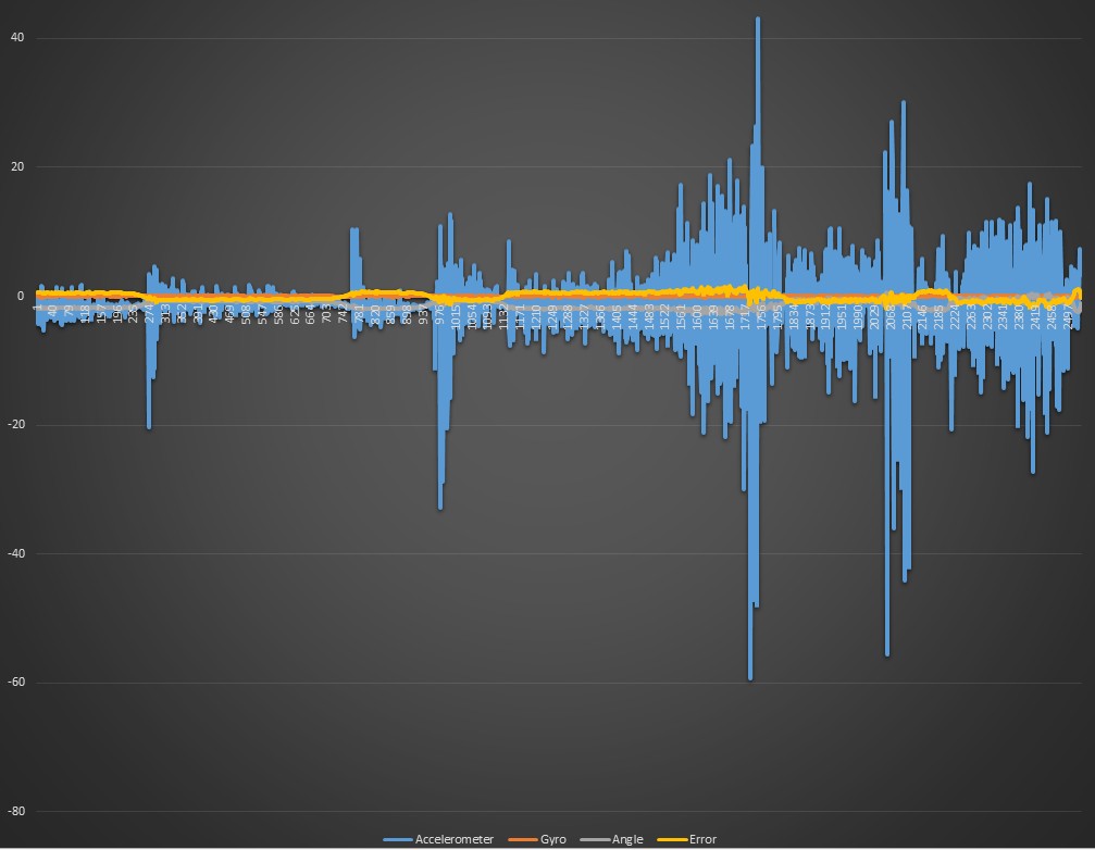
I also went through the logs I had generated from the balancing runs a bit more thoroughly. It was interesting to see how noisy the accelerometer actually is. Here below is a graph from the last weekend's balancing run. This contains 25 seconds of the robot balancing. It has several moments where the robot began to slightly shake near the middle range, and the log shows clearly how the accelerometer (blue graph) gets very high angle values, up to +/- 50 degrees, even though the robot actually stays close to vertical all the time. The complementary filter uses 98% of the gyro angle value and only 2% of the accelerometer angle value, so the accelerometer noise gets smoothed out.
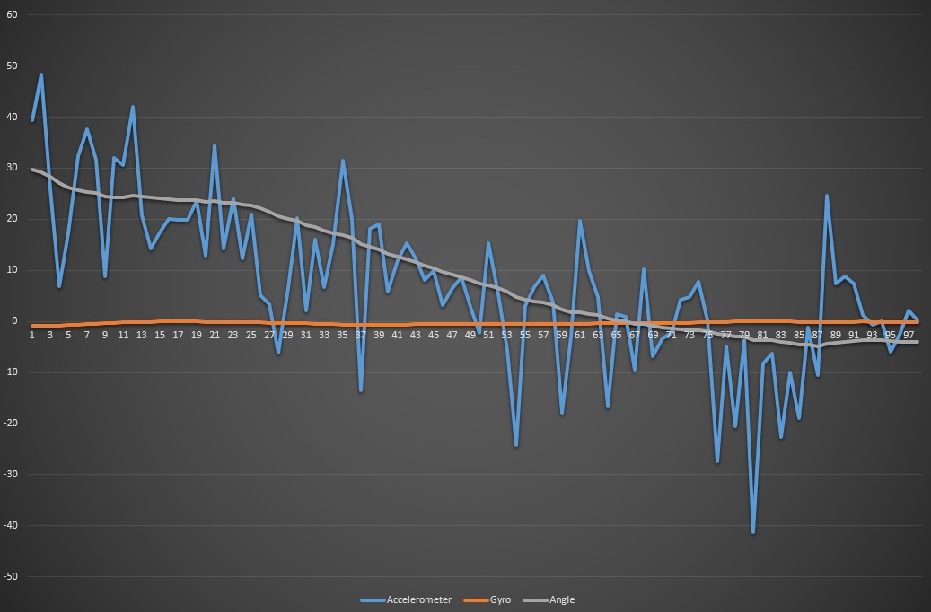
The accelerometer values are actually only used to correct the gyro drift. This can easily be seen from the graph I took when lifting the robot up. I start up my robot in the face-down position, and then lift it up, let the complementary filter calculate the proper tilt angle, and only then put the robot down and let it start balancing. Here below is the graph of the first second of the balancing algorithm. The balancing starts when the calculated angle is between -30 and 30 degrees, so also the logging starts only after the filtered angle gets between these values. The log clearly shows that the gyro angle (orange line) stays close to zero. The accelerometer angle, while very noisy, tells the actual tilt angle when averaged over a longer time period. Within about a second after lifting the robot up, the filtered angle gets pretty close to the actual angle of the robot, so the balancing can start.
Piro head work
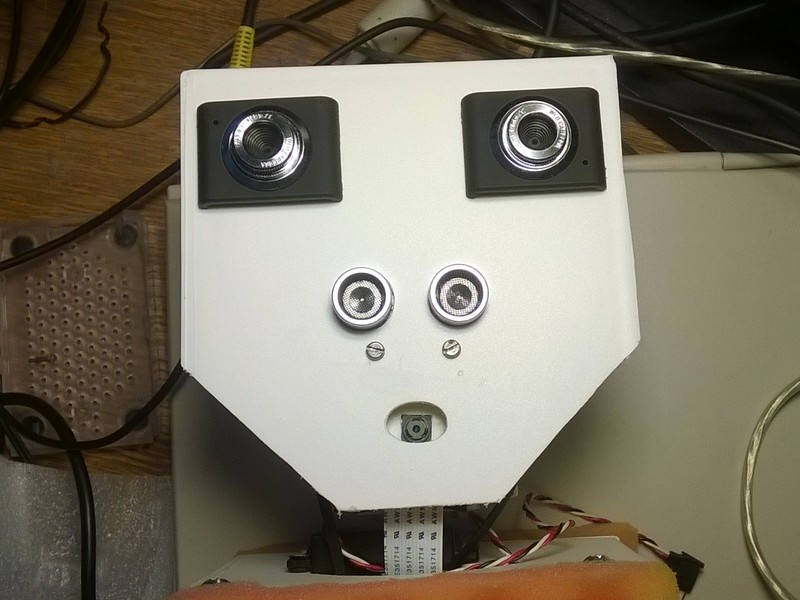
This weekend I worked on building the head for Piro. In my balancing attempts I only had a plastic holder for the Pi Camera as the head. I had been pushing back building the actual head mainly because I was not sure what to do with the ultrasonic sensor. As I wanted to use the web cameras as eyes (and the Raspberry Pi camera as a mouth), I though the ultrasonic sensor might work as a nose, but I was afraid it would look pretty stupid.
This Saturday I finally made some tests in the 3D software I use, and after experimenting with various options, it looked like the ultrasonic sensor as a nose might actually work. I did not want my robot to look threatening, but looking a bit silly would be fine. I spent most of Saturday cutting suitable holes to the part of another VHS cassette case I planned to use as the head, and in the end I managed to get the head built and connected to the head servo and the plastic Pi Camera holder I had built earlier.
Voltage converter pin soldering
I was not happy with the way I had soldered wires to the original LM2596 voltage converter. The input power wires were soldered directly to the on/off switch and ground wire of my robot, and the output was originally soldered to the micro USB wire. After I got the new 5V UBEC, I soldered the micro USB connector wire to that, so the original voltage converter had just some wires without any connector hanging from it. I wanted to use it to power the stereo amplifier, but did not want to solder it directly to the amplifier because the amplifier is in the front part of the robot case and I wanted to keep all power systems in the back part of the case. I wanted to have connectors between all components in the front case half and the back power case half, so I can easily disassemble my robot.
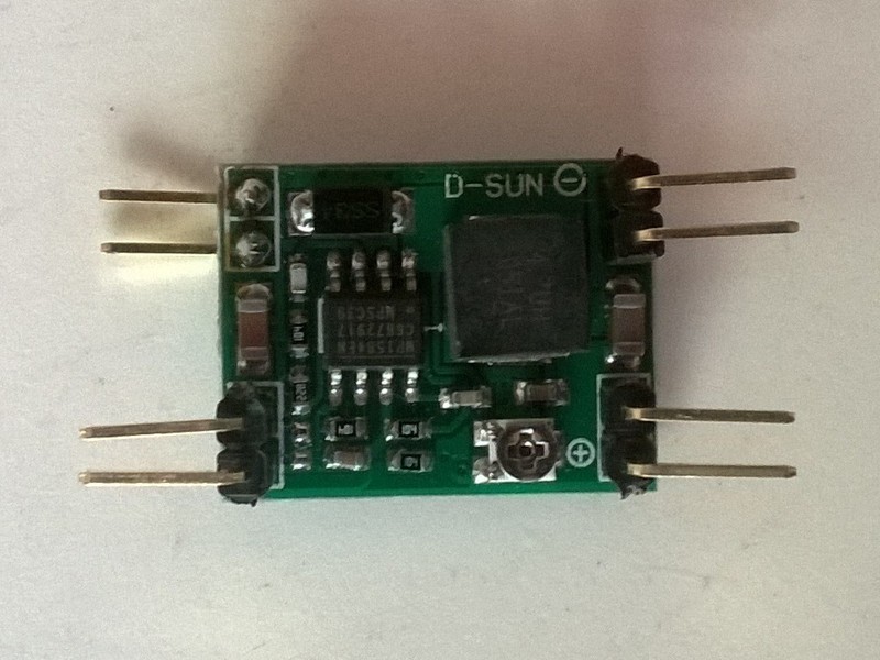
It had suddenly occurred to me that the gyro came with both a straight 8-pin connector and an angled 8-pin connector, and I had only used the straight pin connector. Perhaps I could repurpose the angled connector for the voltage converter? I could then use the female jumper wires to easily connect the components to the voltage converter.
I soldered off the wires from the voltage converter, and actually only then noticed that it had double inputs and outputs. This gave me an idea to cut the original 8-pin connector to 2-pin parts (instead of single pins), and then solder these to the voltage converter. As I am still pretty lousy with soldering it took some time, but in the end I managed to solder all eight pins properly. The input ground pins are on the back side of the circuit board on purpose, as I plan to use those as part of the way I attach the voltage converter to the robot case.
I still need to improve the way the capacitors and the UBEC are attached to the robot case, but I think I will leave that to next week. Now I plan to continue working on the software side, the first step is to get rid of the OpenCV dependencies, and after that I try to import the Pocket Sphinx code to my Piro code.
Aug 16th, 2015 - First succesfull balancing!
I started my balancing attempts today by first changing the logarithmic PWM table to a linear table, and then began tuning the PID algorithm multipliers. I started with the Kp value of 23, which was what I came up with yesterday. That turned out to be too small a value, so I kept increasing it, and I also adjusted the target angle as it began to look like my original (estimated) target angle of -2 degrees was not quite correct. After some tuning I got my robot to stay upright (with just a little bit of help when it speeded up a bit too much and looked like it was about to fall)! Here is the YouTube video I recorded after it began to look like my robot can actually stay upright for a while. This is unedited as I wanted to record the exact behavior of the robot, so I could then compare the video with the logs.
In the end I ended up with the Kp value of 37, and target angle of -1.30. I tried several times increasing the Ki and Kd multipliers, but both of those just caused shaking near the middle range. But now that I know the hardware of the robot is suitable for balancing, I can tune the actual algorithm with no hurry.
Aug 15th, 2015 - Almost succesful balancing attempts!
Today I finally was able to test the balancing of my robot again. I had replaced the Kalman Filter with a simpler complementary filter. I had also built a logging system, as I suspected my 100Hz timer somehow fails to run at that speed, which would explain the delay in the motor direction change.
The first observation was that the robot did not reboot any longer! Cool, perhaps adding the capacitors finally fixed that problem. The next problem was the slow wheel direction change. I looked at the log result, and noticed that my timer code does indeed run at very clean 10 ms intervals, or at 100Hz. Why it does not rotate the wheels properly, then? My PID implementation was very simple, with only the P multiplier in use for the PID controller, and the code was basically just a couple of simple multiplications, why does it not work? It took me quite some time to stare at my code and stare at the log file, until I noticed that it looked like the accelerometer angle and the gyro angle actually seemed to move to the opposite direction!
I realized that when I moved my gyro to between the motors and oriented it differently, I had only checked that the accelerometer values change and the gyro values change when I tilt the robot, but I had not checked the sign of the change! I switched the sign of the gyro measurement, and then tested the wheel action again. Okay, now the wheels finally reversed direction immediately when the tilt angle went over vertical!
Next, I put the robot on the floor and began tuning the balancing algorithm. I managed to get it to stay upright for a few seconds at a time, but it looked like when the tilt angle increased it did not correct the angle quite soon enough. But the whole balancing behavior was heaps more controlled than with my earlier attempts, so it looks like the gyro placement is actually pretty important. The gyro between the wheels seemed to be the perfect placement.
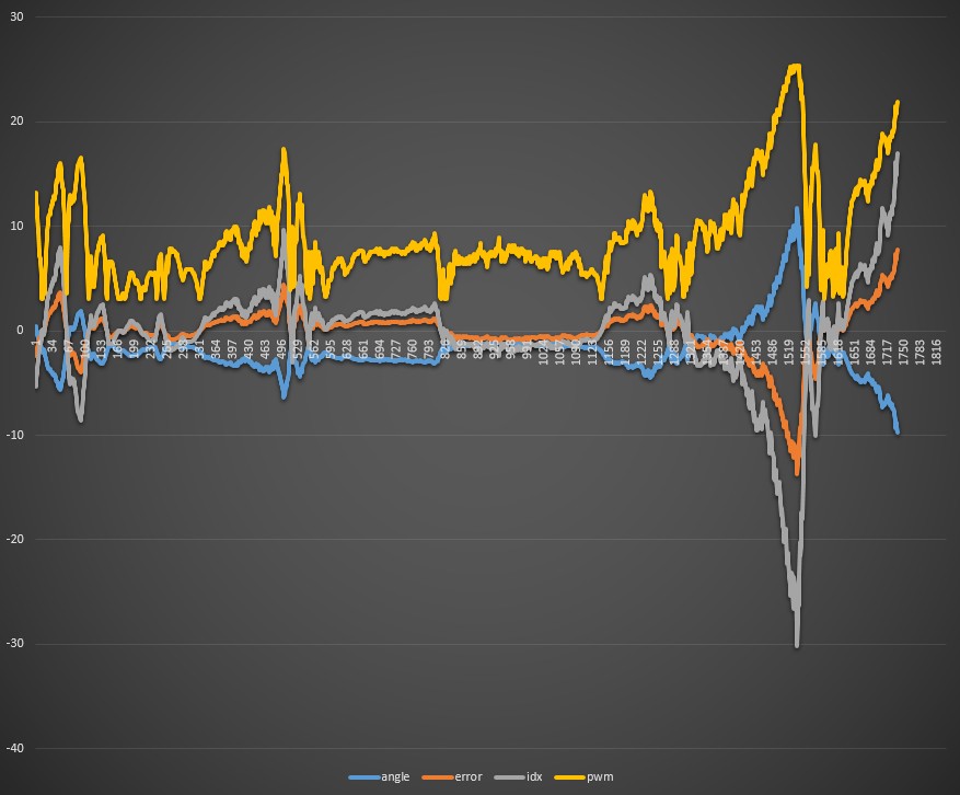
It was starting to get late and I was tired, so I decided to continue the balancing attempts tomorrow after a good night's rest. Here above is a graph from the logs of one of my balancing attempts from today. The horizontal axis is time (in 10ms units), and the blue color is the measured angle (after the complimentary filter), orange is the error value (in practice a mirror of the angle), gray is the index to the pwm table (scaled to fit the graph nicely), which is practically just the error value times the PID controller P multiplier, and the yellow is the resulting pwm value from the table. The table has a bias and a logarithmic scale, and it began to look like my original idea of using a logarithmic scale was a bad one. I decided to try with a simple linear scale for the tests tomorrow.
Aug 14th, 2015 - Added capacitors
I spent the last couple of days googling for possible reasons for a robot controller rebooting, and found some interesting electronics articles that pretty much said that whenever you have trouble with electronics devices, add capacitors. I had some old power source (from an old matrix printer or some such) that had one (very big and heavy!) 10000μF capacitor, one 6800μF capacitor, and a couple of 470μF capacitors. I decided to add the 6800μF capacitor to the input power lines from the battery, and the 470μF capacitor to the micro USB connector wires going to the Raspberry Pi. I did not yet have time to test whether this has any effect, though.
Aug 12th, 2015 - Reboot problems continue!
Today the 5V UBEC I ordered to get rid of the under voltage problems arrived. I quickly soldered it to the micro USB connector, built my robot back together, and continued the balancing tests. Things did not look at all good, as I noticed that when the robot tilted, the wheels began to turn OK, but when I tilted the robot to the other way the wheels still turned to the original direction for almost a full second before they reversed direction! There is no way a balancing robot would stay balanced with such a delay in the motor direction change. However, when I was testing this further, my Raspberry Pi rebooted again!
That was quite frustrating. Firstly, I had just yesterday managed to reinstall my SD card, and it again rebooted, which probably was the reason why the SD card got corrupted earlier! Secondly, my new 5V UBEC (which actually gives 5.30 volts) should have fixed the under voltage rebooting problem! The red led was lit all the time, so I began to suspect that the reboot problem was perhaps not caused by under voltage after all. But what could cause it, then?
Aug 11th, 2015 - SD card reinstall
Today my Raspberry Pi stopped working properly. The shell session stopped responding when I tried to compile my code (immediately after giving the make command). Using a separate shell session I was able to run dmesg and found a lot of SD card read error messages. Pretty annoying. I was able to back up most of my stuff, but still I did not look forward to reinstalling everything. I suspect it was the sudden reboots and constant low-voltage problems earlier that somehow corrupted the SD card.
While reinstalling the SD card I wrote a proper guide for myself about all the steps needed, where to download which software, and so on. I had to rebuild the whole OpenCV installation, which took several hours, so I decided to stop using the OpenCV at all as soon as possible. Currently I only use it for XML parsing and nothing else (as all the face detection code that I use is actually copied to my own source modules). I'll copy the XML parsing code as soon as I can get around to it. I managed to get my Raspberry Pi reinstalled and back to running today, but did not have time to do much else.
Aug 8th, 2015 - Pocket Sphinx profiling continues
For the past couple of days I have been experimenting with the ASM conversion of the eval_cb routine in Pocket Sphinx. I managed to convert much of the code to NEON ASM, and was very interested to test out my new code, expecting notable improvement in the speed. The result was the following (feel free to compare this to the original results from the previous blog post):
      %   cumulative   self              self     total
 time   seconds   seconds    calls   s/call   s/call  name
 21.23      6.03     6.03                             eval_cb_asm
 12.36      9.54     3.51      515     0.01     0.01  prune_nonroot_chan
  9.16     12.14     2.60  5967693     0.00     0.00  hmm_vit_eval
Well, that was pretty disappointing. The original C language eval_cb took 21.24% of the total
time, my shiny new NEON-optimized eval_cb_asm takes only 21.23% of the total time. How nice.
I again googled for NEON optimizations, thinking that perhaps I had misunderstood something (as this was my first ever attempt to use NEON opcodes). I found an example that used PLD opcodes to preload the data cache, so I thought I could experiment with that and see what happens. I added some pld [r4, #32] opcodes (like in the example I found), with the following profiling result:
      %   cumulative   self              self     total
 time   seconds   seconds    calls   s/call   s/call  name
 16.79      4.59     4.59                             eval_cb_asm
 12.77      8.08     3.49      515     0.01     0.01  prune_nonroot_chan
 10.54     10.96     2.88  5967693     0.00     0.00  hmm_vit_eval
Okay, this is looking better! The time spent in eval_cb_asm dropped from 6.03 seconds to
4.59 seconds, using the exact same input. I tested with different values to preload the
cache with, and it looked in this specific algorithm the value of #128 resulted in the
fastest code:
      %   cumulative   self              self     total
 time   seconds   seconds    calls   s/call   s/call  name
 13.64      3.55     3.55      515     0.01     0.01  prune_nonroot_chan
 13.30      7.01     3.46                             eval_cb_asm
 11.34      9.96     2.95  5967782     0.00     0.00  hmm_vit_eval
This actually dropped my eval_cb_asm to the second place, but that is just caused by
normal variation in the gprof results. Still, the time spent went down to 3.46 seconds.
After these tests, I decided to look into using different search types and language models. I also converted the eval_topn routine, which was very similar to eval_cb, into NEON ASM code. This is not called nearly as often so the total speedup is not very dramatic. I checked using the turtle language model and keyword search what the speedups now looked like. Here is the result using the original C code:
      %   cumulative   self              self     total
 time   seconds   seconds    calls  ms/call  ms/call  name
 74.73      2.10     2.10    39237     0.05     0.05  eval_cb
  8.19      2.33     0.23    53928     0.00     0.00  eval_topn
  4.63      2.46     0.13      642     0.20     0.20  ptm_mgau_senone_eval
And then with my NEON ASM code:
      %   cumulative   self              self     total
 time   seconds   seconds    calls  ms/call  ms/call  name
 67.94      1.25     1.25                             eval_cb_asm
 10.87      1.45     0.20      642     0.31     0.31  ptm_mgau_senone_eval
  5.43      1.55     0.10                             eval_topn_asm
So, time spent in eval_cb drops from 2.1 seconds to 1.25 seconds, and time spent in
eval_topn from 0.23 seconds to 0.10 seconds. These were worthwhile speedups, and I
still had not looked into speeding up the ptm_mgau_senone_eval code. Since
over two thirds of the total time is spent in eval_cb, though, speeding up the
other routines will not bring a lot of overall speed improvement to the code.
Aug 4th, 2015 - Pocket Sphinx profiling
Okay, today I finally got around to running gprof with Pocket Sphinx, when it tries to recognize speech from my test wav file, with all the parameters using the default values. After getting the gprof result I looked at the objdump disassembly of the most time-consuming routine, and got quite confused as the disassembly did not seem to match the source code. It took me a while to realize that I had accidentally built the code with the FIXED_POINT define on. Thus all the floating point calculations actually used fixed point integer arithmetic. After fixing this, and also changing many static functions to non-static (so that the compiler does not inline them automatically), these were the most time-consuming routines:
      %   cumulative   self              self     total
 time   seconds   seconds    calls   s/call   s/call  name
 21.24      6.15     6.15   113943     0.00     0.00  eval_cb
 12.02      9.63     3.48      515     0.01     0.01  prune_nonroot_chan
  9.39     12.35     2.72  5967692     0.00     0.00  hmm_vit_eval
  7.91     14.64     2.29     1545     0.00     0.00  ptm_mgau_senone_eval
  6.84     16.62     1.98  5967727     0.00     0.00  acmod_activate_hmm
  4.56     17.94     1.32  2691234     0.00     0.00  find_bg
I started looking into the eval_cb (evaluate code books) routine, trying to understand
what it does and figuring out ways to improve it.
Aug 3rd, 2015 - Pocket Sphinx rebuilt from sources
I wanted to optimize and convert the most time-consuming code to ASM also in the Pocket Sphinx routines, so I decided to start building the pocketsphinx_continuous directly from the sources using my own Makefile, so that it does not generate a library but a monolithic executable that I can then profile. It took me pretty much the whole day to get it to build, as I just added one source file (and one header file) at a time. This was time well spent, though, as I got a good understanding about which routines are in which source modules.
Aug 2nd, 2015 - OpenCV 3.0 FaceRecognizer missing?
After I got face detection working and slightly optimized, I decided to look into face recognition as well. However, after googling the OpenCV face recognition examples and then trying to run the same in my Raspberry Pi, it looked like my OpenCV 3.0 version did not have the FaceRecognizer class at all. After some more googling I found a StackOverflow question about this issue, and it turned out that the FaceRecognizer class is in the contrib module, which by default is not included with OpenCV 3.0.
I decided against installing the contrib module as I won't be using it as-is anyways, instead I Looked at the source codes in the GitHub repository. I can download the sources straight from there when I actually start working on face recognition. However, I decided that getting speech recognition working is actually more important than face recognition, as the former is a needed feature if I want to run my robot in an environment where it can not access wireless network, while face recognition is just something that would be cool to have.
Aug 1st, 2015 - OpenCV ASM conversion work
Since the last blog post I have managed to port all the face detection code of OpenCV to plain C. This obviously got rid of the C++ error messages, so now the face detection runs nicely. I also found out that the original OpenCV face detection implementation is actually multi-threaded, which was a bit of a surprise. I had planned to use only one thread for face detection in piro, as I want to have dedicated threads for different tasks. It may be that the original OpenCV C++ implementation (which was already running when I made my first balancing tests) may have caused problems with the balancing code, as I had assumed my balancing code ran in a thread (and CPU core) dedicated to it. But if the OpenCV also launched 4 threads to run the face detection, the balancing code had to task switch with the OpenCV face detection code!
I made my C implementation to only run in a single thread, which also meant that it runs now almost four times slower than the original multi-threaded C++ implementation. However, I do not plan to leave my implementation in C, but instead I am converting the most time-consuming parts to hand-tuned ASM, using NEON code where possible. It took some time for me to figure out how the C++ code works, but now I have a pretty clear understanding of how the Haar cascade detection works.
While converting the code to C, I also optimized the code somewhat, for example left out all the code that none of the face detection cascades seemed to use. I also moved all the code that adjusts the scales for the input frame size to not run for every frame, as I do not plan to change the frame size while my code is running. I calculated the scales when loading the cascade from the XML file, and after that I just always use the same input image size when doing the actual face detection. After a couple of days working on this I had the code running and giving correct detection results.
When deciding what code to optimize next, I used gprof to see approximately how much time each routine takes. This is the result from my C code when running the detection for 50 frames:
    Each sample counts as 0.01 seconds.
  %   cumulative   self              self     total
 time   seconds   seconds    calls  ms/call  ms/call  name
 37.03      3.34     3.34 33616873     0.00     0.00  HaarEvaluator_OptFeature_calc
 23.95      5.50     2.16   632253     0.00     0.01  predictOrderedStump_HaarEvaluator_
 23.73      7.64     2.14  5622411     0.00     0.00  HaarEvaluator_setWindow
 11.31      8.66     1.02     1250     0.82     0.82  integral_
  2.77      8.91     0.25  5622411     0.00     0.00  CascadeClassifierImpl_runAt
  0.89      8.99     0.08       50     1.60   159.41  CascadeClassifierInvoker_Range
  0.11      9.00     0.01     2913     0.00     0.00  HaarEvaluator_Feature_read
  0.11      9.01     0.01       50     0.20    20.60  FeatureEvaluator_setImage
  0.11      9.02     0.01        1    10.00    20.00  LoadFaceClassifier
As that shows, it took about 9 seconds to run the face detection for 50 frames, so the
detection rate is pretty poor, around 5 frames per second, but on the other hand it is
only running in one thread versus the original implementation's four threads.
This is what I used as my starting point when optimizing the code.
The HaarEvaluator_OptFeature_calc routine is performing the actual detection work, and it looked too simple to get any worthwhile optimizations done working on that, so instead I began working on the integral_ routine. Integral is one of the image transformation algorithms in the image processing module of OpenCV. I checked using objdump what sort of an ASM conversion the GCC compiler comes up with for this routine, and found some room for improvement. First, this is the main loop of the integral calculation (you can find this in the OpenCV sources in the file modules/imgproc/src/sumpixels.cpp):
        for( y = 0; y < size.height; y++, src += srcstep - cn, sum += sumstep - cn, sqsum += sqsumstep - cn )
        {
            for( k = 0; k < cn; k++, src++, sum++, sqsum++ )
            {
                ST s = sum[-cn] = 0;
                QT sq = sqsum[-cn] = 0;
                for( x = 0; x < size.width; x += cn )
                {
                    T it = src[x];
                    s += it;
                    sq += (QT)it*it;
                    ST t = sum[x - sumstep] + s;
                    QT tq = sqsum[x - sqsumstep] + sq;
                    sum[x] = t;
                    sqsum[x] = tq;
                }
            }
        }
Looking at the code the compiler generated, I found that it performed a lot of stack
access in the innermost loop. The algorithm itself did not seem so complex, and I was
sure I would be able to fit everything into the CPU registers for the loops. I did that,
and was able to get some improvements to the speed, but this did not much change the
overall speed. However, I noticed that the original code actually does this when it
calls the integal routine (see the method FeatureEvaluator::setImage in the file
modules/objdetect/src/cascadedetect.cpp):
        for (i = 0; i < nscales; i++)
        {
            const ScaleData& s = scaleData->at(i);
            Mat dst(s.szi.height - 1, s.szi.width - 1, CV_8U, rbuf.ptr());
            resize(image, dst, dst.size(), 1. / s.scale, 1. / s.scale, INTER_LINEAR);
            computeChannels((int)i, dst);
        }
(The computeChannels routine above is what actually calls the integral
algorithm.) The code goes through all the image scales (there are 25 scales for a
320x240 input image, more scales for larger input images) and actually resizes (using
linear interpolation) the original input image for each of these scale sizes, and then
performs integral over this resized image. The resized image is then immediately
discarded, it is only used for the integral calculation.
I thought this seemed very wasteful, and since the whole face detection is using approximations, I did not see why it could not interpolate over the original input image while performing the integral calculation. Thus, I began working on a version of the integral algorithm that would always get the same original input image as the parameter, together with the scaling factor, and would then interpolate over this image when calculating the integrals.
I came up with the following code, which runs at about half the time of the original integral calculation, and on top of that it does not need the input image to be copied and resized for every scale step. To fit everything into registers I had to hard-code some values, so that this code only works for 320x240 input images. It can be made to work with other sizes as well, but needs to be adjusted for each size separately.
//------------------------ integral_asm_interpolate ----------------------------------------
// Optimized ASM version for calculating integral of an image. This version interpolates
// over the same source image for all the size scales, avoiding creating new images and
// resizing them. The original "intergrate_" C call took 11.31 % of the total face detection
// time, this version takes 5.73%. This does not take into account the additional time saved
// not having to resize the images.
//
//  %   cumulative   self              self     total
// time   seconds   seconds    calls  ms/call  ms/call  name
//  5.73     10.36     0.60                             integral_asm_interpolate
//
// Input:
//    r0 = *src                      (0x18ed20)
//    r1 = _srcstep                  (0x150 (336))
//    r2 = *sum                      (0x70238020)
//    r3 = _sumstep                  (0x580 (1408))
//    [sp, #9*4] = *sqsum            (0x7046c720)
//    [sp, #10*4] = scale<<16
//    [sp, #11*4] = size.width       (0x140 (320))
//    [sp, #12*4] = size.height      (0xf0 (240))
//
// Registers:
//    r0  = temp value
//    r1  = s (row sum)
//    r2  = sq (row squared sum)
//    r3  = src interpolation counter (== x<<16 for src access)
//    r4  = it = src[x] value
//    r5  = x = inner loop counter
//    r6  = src pointer
//    r7  = sum - sumstep pointer
//    r8  = sqsum - sqsumstep pointer
//    r9  = sum pointer
//    r10 = sqsum pointer
//    r11 = y = outer loop counter << 16
//    r12 = scale<<16
//    lr  = src original value

#define    SRC_WIDTH      320
#define    SRC_HEIGHT     240
#define    SRCSTEP        320
#define    SUMSTEP        1408

integral_asm_interpolate:
    push    {r4-r11, lr}
    mov     r4, r1                        // save srcstep
    cmp     r3, #SUMSTEP                  // ASSERT: Is sumstep == 1408 ?
    bne     3f                            // Exit if not!
    mov     r6, r0                        // r6 = src pointer = first input parameter
    ldr     r8, [sp, #(9*4)]              // r8 = sqsum input pointer
    //------
    //    sum += sumstep + 1;
    //------
    add     r7, r2, #4                    // r7 = sum - sumstep pointer (sum += sumstep + 1, sum[x - sumstep])
    add     r9, r7, #SUMSTEP              // r9 = sum pointer
    //------
    //    sqsum += sqsumstep + 1;
    //------
    add     r8, #4                        // r8 = sqsum - sqsumstep pointer (sqsum += sqsumstep + 1, sqsum[x - sqsumstep])
    add     r10, r8, #SUMSTEP             // r10 = sqsum pointer
    //------
    //    memset( sum, 0, (size.width+1)*sizeof(sum[0]));
    //------
    mov     r0, r2                        // r0 = sum (input pointer)
    ldr     r11, [sp, #(11*4)]            // r11 = size.width
    mov     r1, #0
    add     r2, r11, #1                   // r2 = size.width + 1
    lsl     r2, #2                        // r2 = (size.width+1)*sizeof(sum[0])
    bl      memset
    //-----
    //    memset( sqsum, 0, (size.width+1)*sizeof(sqsum[0]));
    //-----
    sub     r0, r8, #4                    // r0 = sqsum (input value)
    mov     r1, #0
    add     r2, r11, #1                   // r2 = size.width + 1
    lsl     r2, #2                        // r2 = (size.width+1)*sizeof(sum[0])
    bl      memset
    //------
    // Setup the registers for the loops
    //------
    mov     r11, #0                       // y = 0;
    ldr     r12, [sp, #(10*4)]            // r12 = scale<<16 (loop incrementer value)
    mov     lr, r6                        // lr = src start position
    //------
    //    for( y = 0; y < size.height; y++, src += srcstep, sum += sumstep, sqsum += sqsumstep )
    //    {
    //------
2:
    //------
    //        int s = sum[-1] = 0;
    //        int sq = sqsum[-1] = 0;
    //------
    mov     r1, #0                        // int s = 0;
    mov     r2, #0                        // int sq = 0;
    str     r1, [r9, #-4]                 // sum[-1] = 0;
    str     r2, [r10, #-4]                // sqsum[-1] = 0;
    //------
    //        for( x = 0; x < size.width; x += 1 )
    //        {
    //------
    mov     r5, #0                        // x = 0;
    mov     r3, #0                        // x = 0; (for src interpolation)
    //------
    //            uchar it = src[x];
    //            s += it;
    //            sq += (int)it*it;
    //            int t = sum[x - sumstep] + s;
    //            int tq = sqsum[x - sqsumstep] + sq;
    //            sum[x] = t;
    //            sqsum[x] = tq;
    //------
1:  ldrb    r4, [r6, r3, lsr #16]         // r4 = uchar it = src[x];
    ldr     r0, [r7, r5, lsl #2]          // r0 = sum[x - sumstep]
    add     r1, r4                        // r1 = s += it;
    add     r0, r1                        // r0 = t = sum[x - sumstep] + s;
    str     r0, [r9, r5, lsl #2]          // sum[x] = t;
    ldr     r0, [r8, r5, lsl #2]          // r0 = sqsum[x - sqsumstep]
    mla     r2, r4, r4, r2                // r2 = sq += it*it;
    add     r0, r2                        // r0 = tq = sqsum[x - sqsumstep] + sq;
    str     r0, [r10, r5, lsl #2]         // sqsum[x] = tq;
    //-----
    //        }
    //-----
    add     r5, #1                        // x += 1
    add     r3, r12                       // x (for src interpolation) += scale<<16
    cmp     r3, #SRC_WIDTH<<16            // x < size.width ?
    blt     1b                            // Back to x for loop if x < size.width
    //-----
    //    }
    //-----
    add     r11, r12                      // y += scale << 16
    mov     r6, r11, lsr #16              // r6 = y value
    mov     r0, #SRCSTEP
    mla     r6, r0, r6, lr                // src += srcstep (r6 = SRCSTEP * (y>>16) + src original pointer)
    add     r7, #SUMSTEP                  // (sum - sumstep) += sumstep
    add     r8, #SUMSTEP                  // (sqsum - sqsumstep) += sqsumstep
    cmp     r11, #SRC_HEIGHT<<16          // y >= size.height ?
    add     r9, #SUMSTEP                  // sum += sumstep
    add     r10, #SUMSTEP                 // sqsum += sqsumstep
    blt     2b                            // Back to y loop if y < size.height
3:  pop     {r4-r11, pc}                  // Return to caller
July 27th, 2015 - OpenCV C conversion work
I have had OpenCV face detection code working in the piro software using the Pi Camera for a while now, but the problem is that I get some "pure virtual method called" error and then a crash always when I shut down my software. This is some C++ thingy, and as I am not very familiar with C++ (and plan to never become familiar with it!), the OpenCV calling code is the only place I use C++ in my code. I decided I wanted to get rid of all the C++ code in my software, and thus I began porting all the face detection OpenCV C++ code to plain C.
The first problem was parsing the XML cascade files, but after some googling I found a C api for the XML file reading, and after some work I managed to read in the Haar face cascade XML files into my C code. The next step is to convert the actual C++ face detection code, starting with the lowest level routines and working my way upwards.
July 26th, 2015 - New motor mounting brackets and gyro placement
For the past couple of days after my failed balancing attempts I have been working on the software side of things, but today I decided to build the new motor mounting brackets for the coming wheel adapters. Originally I had mounted the wheels inside out, so that the wheels were oriented outward from the motor shaft. However, the new wheel adapters that I ordered needed the wheels to be mounted properly, so that the motor is actually partly inside the wheel. Thus I needed to build new mounting brackets that move the motors further apart (for the wheels to clear the robot chassis properly).
I measured that the motor will be up to 13mm inside the wheel. The brackets should be as wide as possible to make them as strong as possible, but not so wide that the wheel does not have room to rotate properly. The wheel inside diameter is 52mm, and the motor diameter is 25mm, so after some calculations I ended up with 35mm being a safe width. I built the new mounting brackets and mounted the motors to them, and luckily the motor wires were (just barely) long enough that I could still use the same wires I had originally soldered to the motors to connect the motors to the L298N controller.
I also suspected that perhaps my gyro placement was a factor in the failed balancing attempts. I had read that the general consensus is that the gyro should be as close to the wheel rotational axle as possible, so I decided to put the gyro exactly between my motors, now that I had room there. I built a mounting bracket for the gyro there. I used the same insulated holes I had drilled to the aluminum chassis for the motor wires to bring the gyro wires through the aluminum chassis. I was a bit worried that the motor current may cause EM interference to the gyro signal wires, but hoped that would not be the case. I was pretty happy with the end result.
July 23rd, 2015 - Raspberry Pi reboot problem
I started testing my PID algorithm changes today, but after the first failed try, my Raspberry Pi rebooted when I put my robot back down to horizontal. I had coded my PID controller so that if the angle is between -30 and +30 degrees from vertical, the motors are enabled, else the robot thinks it has fallen down and shuts down the motors.
It was strange that it would reboot after shutting down the motors. I tried again, but it rebooted again pretty much right after I had lifted my robot up, and then when I put it down again, it went into a reboot loop. It started booting, then immediately rebooted, on and on. I had to power it down, worried that I had broken down my Raspberry Pi, or at least corrupted the SD card. When I connected it to my normal USB power source, it booted up normally, though. But I can not continue my balancing attempts until I have figured out the reason for these reboots.
Googling for potential reasons for sudden reboots, I ran across a forum post about Under-voltage warnings. I had been wondering what that colorful square always on the top right corner of the screen is, and why the red led on the board itself only blinks once during the boot and then never lights up again while the Pi is running! Turns out I have been giving it too low a voltage all the time!
I decided to order a proper 5V UBEC device from DealExtreme, as that was mentioned to have been used specifically for Raspberry Pi. Since I also had some problems during my balancing attempts with the Meccano wheel adapters (a couple of times one of the wheels almost fell off as the bolt got loosened), I decided to order proper 12mm hex wheel adapters for 4mm shaft from an online store in England, as I did not find those from DealExtreme. It was a bit silly to pay about twice the value of the actual adapters as postage, but I did not want to always keep tightening the bolts with the poorly fitting Meccano adapters.
Too bad this will cause a two week delay for my balancing attempts, but at least I don't need to worry about the original voltage converter suddenly giving too much voltage to my Raspberry Pi.
July 22nd, 2015 - Motor installation, GPIO wiring, first balancing attempts!
Okay, a busy day! I started pretty early by soldering the wires to the motors and joining them to the L298N controller. Next, I decided on a wiring diagram, which GPIO pin to use for which L298N input pin. This is the wiring diagram for future reference:
- +3.3V  (pin 1)  = MPU6050
- SDA    (pin 3)  = MPU6050
- SCL    (pin 5)  = MPU6050
- GND    (pin 6)  = MPU6050
- GPIO4  (pin 7)  = Motor ENA (brown)
- GPIO17 (pin 11) = Motor ENB (brown)
- GPIO18 (pin 12) = Motor IN1
- GPIO27 (pin 13) = Motor IN2
- GPIO22 (pin 15) = Motor IN3
- GPIO23 (pin 16) = Motor IN4
- GPIO5  (pin 29) = Neck Servo
- GPIO6  (pin 31) = Head Servo
After making the needed changes to my balancing code, it was time for the first balancing attempts! I made several attempts, with various changes to the PID parameters (actually only to the P value, as both I and D were still zero), but the robot just jittered horribly around the middle point. It felt like it always overshot the middle point by a lot, but when I lowered the P value, it just failed to correct the tilt fast enough and fell down even faster.
I was not able to find suitable PID algorithm values, which was a bit frustrating, but on the other hand I did not actually expect to be able to make my robot balance on the first try. Hoped, yes, but did not expect.
Since it looked like the PWM values near the middle point were the problem, I decided to implement a conversion table for the PWM values, using a logarithmic scale. The middle point had low values, then the PWM values ramp up fast in the beginning, and then slower when the tilt angle increases. I plan to test this change tomorrow.
July 21st, 2015 - MPU6050 attached, motors arrived!
Today the motors arrived, cool! Now I pretty much have every component I need to make my robot actually balance! Just need to build some motor mounting brackets and connect everything together. I started by attaching the MPU6050 to the top of my chassis, behind the head servo. I did not have any special reason to put it there, there just happened to be suitable room for it.
Next I soldered some small capacitors to the motor poles, to lessen the high frequency noise they will cause. I learned this trick back in the 80's when working on various R/C models. I also checked that the motors run properly in both directions, and then started work on the motor brackets, and managed to pretty much finish them before stopping work for today. This is getting exciting, not a lot of work remaining to do before I can actually properly start up my robot for the first time!
July 20th, 2015 - Pictures, WiFi connection works!
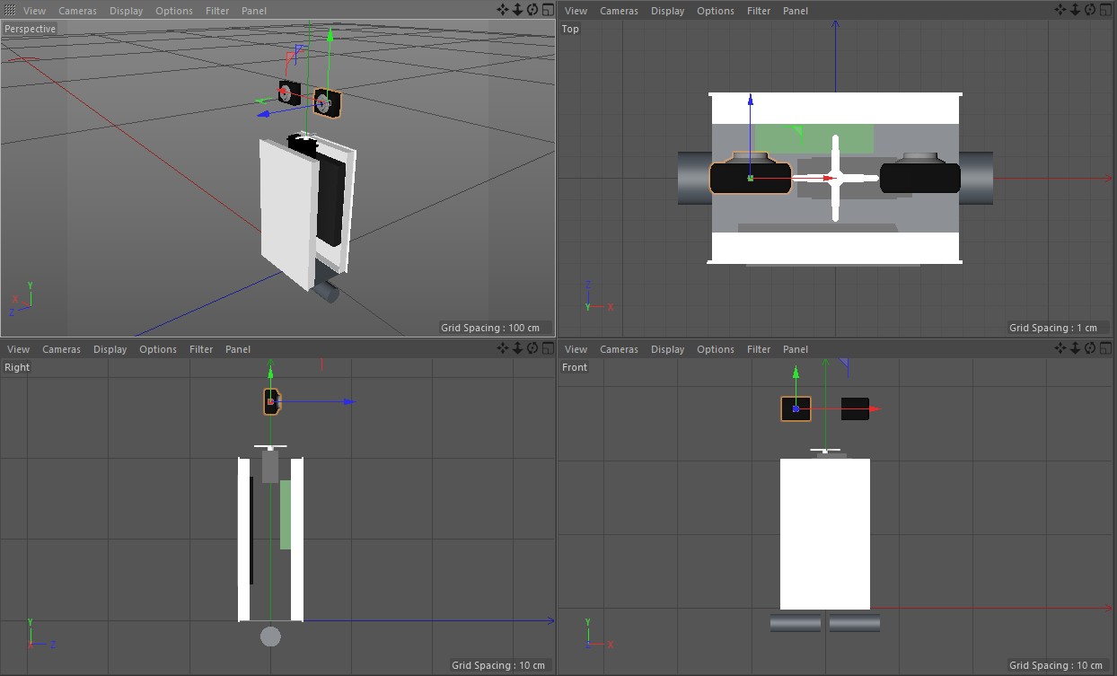
Okay, time to show some more pictures about my progress, together with a new 3D model version.

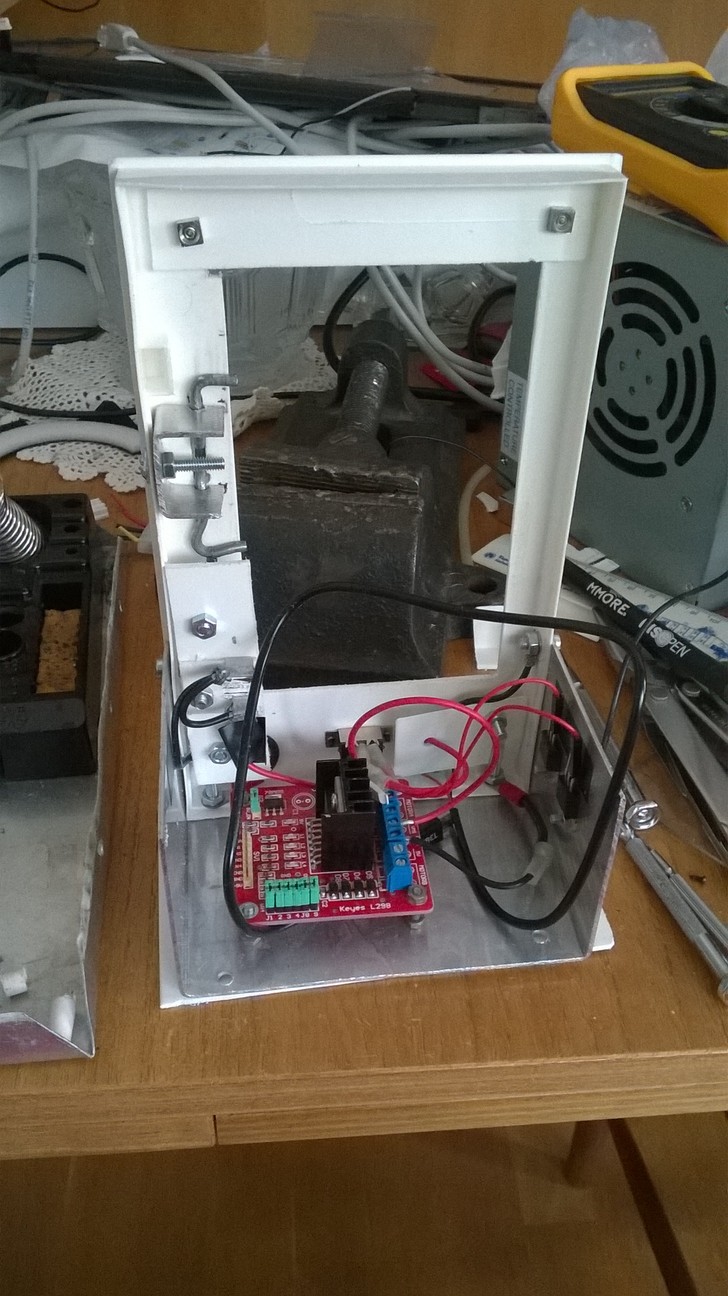
The picture below shows the battery latch system. I have also attached the L298N motor controller to the base aluminum chassis part, and the 5V voltage converter is behind the white plastic part beside the main on/off switch. There are a couple of the L7805 voltage regulators attached to the right hand side wall, they use the large aluminum chassis plate as their heat sink. Thus, this picture actually shows the whole power system of my robot.
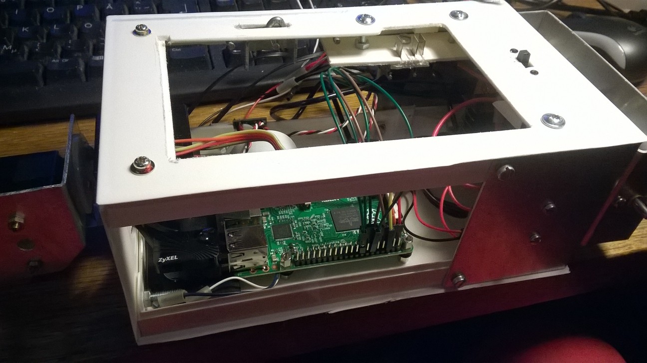
This below is what the front part of the robot now looks like. The two web cameras are not where they will end up, they are just inside the case to keep them from falling off the table. The 4-wire connector from the Raspberry Pi goes to the MPU6050 gyro (which I have not attached yet to the case), the small circuit board attached to the near side of the case is the stereo amplifier, and below the neck servo are the two loudspeakers from the Acer laptop. They fit nicely partly behind the Raspberry Pi and side by side into the case. The 3D image above shows the holes I drilled to the case for the small loudspeaker cones. The Raspberry Pi camera is attached to the head servo.
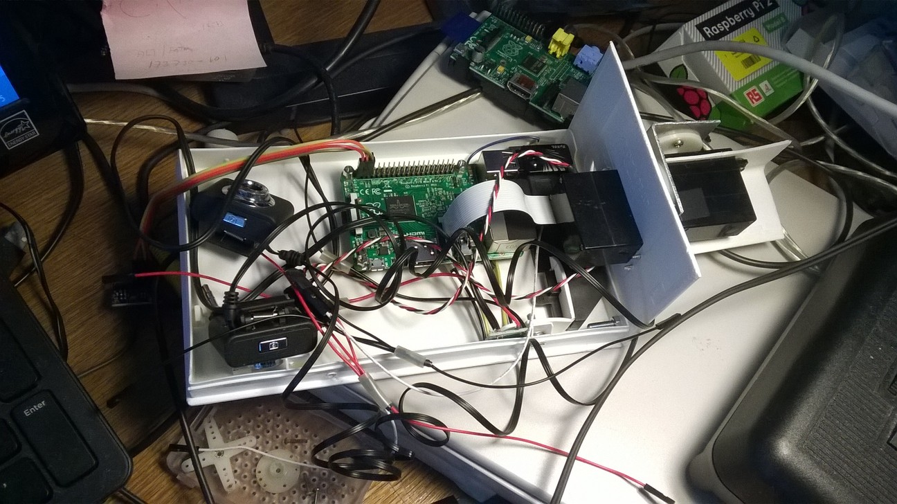
Today I also managed to get the WiFi adapter working finally! You can see the WiFi adapter connected to the Raspberry Pi in the image above. I found information about how to make the adapter connect to an unsecured network here. This is actually very simple, I just needed to add this to the end of the /etc/wpa_supplicant/wpa_supplicant.conf file:
    network={
        key_mgmt=NONE
        priority=-999
    }
This basically means that after trying the known networks, connect to any unsecured
network. Earlier I had tried to figure out how to make it connect to my unsecured network,
using the network ID, but had not figured out a way to set the encryption to none.
July 19th, 2015 - Battery latch work
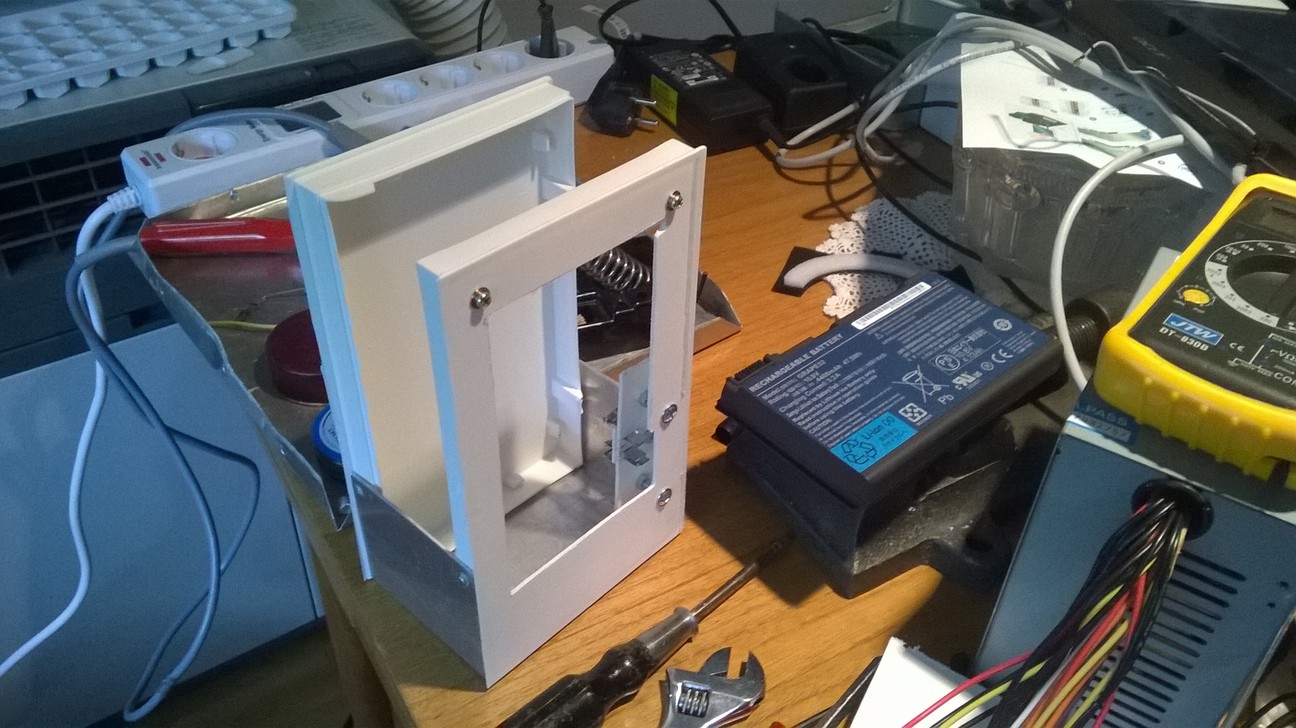
I have been pushing back working on a system to lock the battery properly into my robot. For now the battery just stays in place because I made the hole for it a bit too tight, but in the future when the robot is upright and tries to balance, I need to make sure the battery does not fall off. Today I finally decided to start working on a proper latching system for the battery.
The original laptop has a latch that moves two short 3mm diameter stubs, for which the battery has corresponding holes. Those stubs are only about 2mm in length, so I was not sure if I can make something similar with sufficient accuracy using only my simple hand tools. I decided to try anyways. I found some 3mm aluminum wire, twisted it into a suitable shape, and then began building attachments around the wire so that it would move the required amount but still keep the battery tightly in place. In the end I managed to make it all work, even though it is not the prettiest of constructions. But as long as it works it is fine, right?
July 18th, 2015 - Chassis work continues, balancing code work started
For the past couple of days I have been mainly working on the robot chassis, but today I decided to start working on the PID code for my robot. I included the pigpio library and wrote the Kalman Filter algorithm for the smoothing of the gyro and accelerometer values, and also started on the actual PID algorithm implementation.
July 16th, 2015 - L298N motor controller arrives
Today the L298N package arrived. Thus, I decided to start working on the GPIO access for my piro software. First I needed a good reference for the GPIO pins of my Raspberry Pi 2, which I found from the elinux.org pages.

Then I needed some software to make it easier to access the GPIO pins and to generate PWM signals for the motor speed control. I googled for such and in addition to the ServoBlaster I had used before, I found the pigpio package. At first I thought I would continue using ServoBlaster, until I found a forum post that mentioned it may have problems when playing audio at the same time (it uses by default the same hardware as the audio playing). It was mentioned that pigpio defaults to a method that does not conflict with audio playing, so I decided to download and install pigpio. It turned out to be a very feature-rich system, it has all the servo controls, PWM controls and basic digital on/off controls for all the available GPIO pins.
July 15th, 2015 - Chassis work continues, PID algorithms
For the past couple of days I have been working on the robot chassis. I have also googled for information about the PID controller algorithm that I would need to use for balancing the robot. I found several interesting source code snippets that I will need to study closely when I get around to actually implementing the balancing algorithm for my robot.
- The PiBBOT page by Mark Williams from ozzmaker.com has a good description of the PID controller he used with a Raspberry Pi.
- This Balancing robot final year project Youtube video showcases a robot that seems to be very stable even with extra weights added. The author has shared the source code and various other useful links about the algorithms.
- The Arduino forum has a full thread titled Balancing robot for dummies which has a lot of useful information, regardless of the controller hardware in use.
- The whole PID Controllers: Theory, Design and Tuning book is available online.
- Also interesting is the Caltech Control System Design course book Chapter 6: PID Control.
July 13th, 2015 - Wheels purchased
Today I finally purchased the wheels for my robot. I went to a local R/C shop to see what kind of wheels they had. I only had the specs that they should be at least 80 mm in diameter and should be suitable for a 4mm shaft. They immediately pointed me to 85mm diameter R/C buggy wheels, but said that all of the wheels they had were for the 12mm hex wheel adapter with either 5mm or 6mm shaft. I didn't think that this would be a problem, as I had already checked that I had some parts from an old Meccano construction set that I thought I could use as wheel adaptors.
When I got home I drilled some holes to the wheels where I could attach the Meccano parts. I checked and re-checked the correct location for the drill hole several times, but still managed to drill the first hole to a slightly wrong place for both wheels! That was pretty annoying, but luckily all the other holes I managed to drill properly. It just looks a bit silly when the wheel has one extra hole that is not correctly aligned with the adaptor.
July 12th, 2015 - Chassis work continues
For the past couple of days I have been working on the chassis of my robot. I decided to take some pictures, and I have also started working on a 3D model of the robot in Cinema 4D. I plan to use that to experiment with the location of the various components. I have so far only fixed the location of the battery, as there are not that many places where I can put it in my design. The battery will be kind of a backpack for the robot, with the Raspberry Pi attached to the front part and a servo to turn the head on top of the robot chassis. I still haven't decided what the head should look like (besides the web cameras as eyes), nor have I purchased the wheels so I was not able to model those yet.
July 11th, 2015 - Voltage regulator problems
Today I tested the LM2596 adjustable voltage converter, trying to get it to output 5 volts. I had quite a lot of trouble adjusting the microscopic potentiometer. At first it gave around 4.6 volts, so I decided to adjust it a bit. After a small turn of the potentiometer, it gave 10.4 volts! That much would certainly fry my Raspberry Pi!
I turned it back, but then it gave something like 3.1 volts. Turning just slightly towards the larger values it again gave over 10 volts. I was not able to find anything near 5 volts no matter how little I turned the potentiometer. I got frustrated and turned it as far left as it would go, and when I then measured the voltage, it was exactly 5.00 volts. Strange.. Perhaps that is some sort of a default setting when the potentiometer is set to zero?
Anyways, this makes me a bit nervous about using this voltage converter to power my Raspberry Pi. I decided to always measure the voltage without the Pi connected first, and only if it is still 5 volts, hoping that it stays at that value.
July 10th, 2015 - Web cameras arrive, stereo amplifier works!
Today finally the web cameras arrived! But before that, I had (again very carefully) soldered wires to the extremely tiny stereo amplifier that was in the package that arrived yesterday. From the image on the DealExtreme page I had not realized how small it actually is. It says it is 2cm x 2cm, but you only realize that it means it is the size of your thumbnail (with really tiny wire holes) when you need to solder the wires to it! Anyways, again using great care I managed to solder the wires from the amplifier output to the Acer laptop loudspeaker wires, and an old headphone wire to the input of the amplifier. I then connected the headphone connector to my Raspberry Pi and the output from and adjustable power source to the amplifier, launched my rpix86 on my Raspberry Pi and started Jazz Jackrabbit in it, and the Jazz theme music blasted out of the loudspeakers with a pretty hefty volume! Very cool!
Okay, next I connected one of the web cameras to my Raspberry Pi, and took a picture of myself (with similar lighting conditions as before using the Raspberry Pi camera). The resulting picture is below.
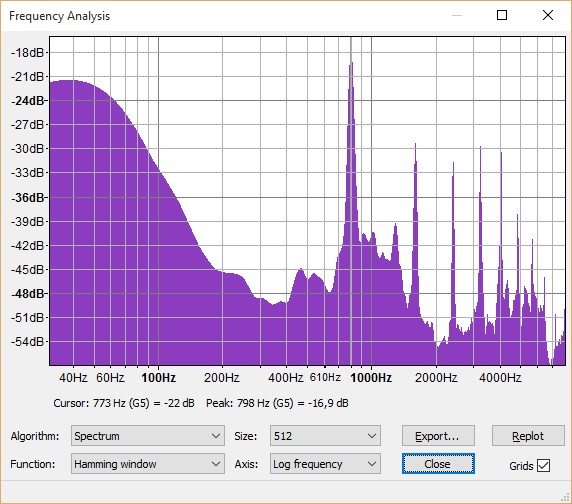
Well, okay... The picture is even worse than with my old web camera. Perhaps with a lot of light the image might be usable, but it is starting to look like I will be using the Pi Camera for all the actual computer vision work. But how about the audio side? I can still use two of these web cameras as two separate microphones, in an attempt to locate the audio sources. I recorded some audio, and played it back, and was surprised to hear quite a lot of low frequency hum. I decided to record some silence, and imported the WAV file to Audacity. Here below is a screen copy of the Audacity frequency analysis of the microphone recording silence.
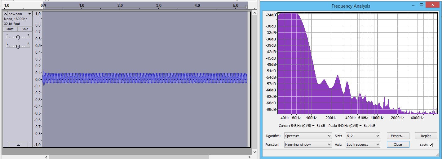
That is actually pretty horrible! I thought that perhaps ordering three of such useless web cameras was just a waste of money, until I decided to test another of the new web cameras. Luckily it had much less noise in the microphone signal, same as the third one.
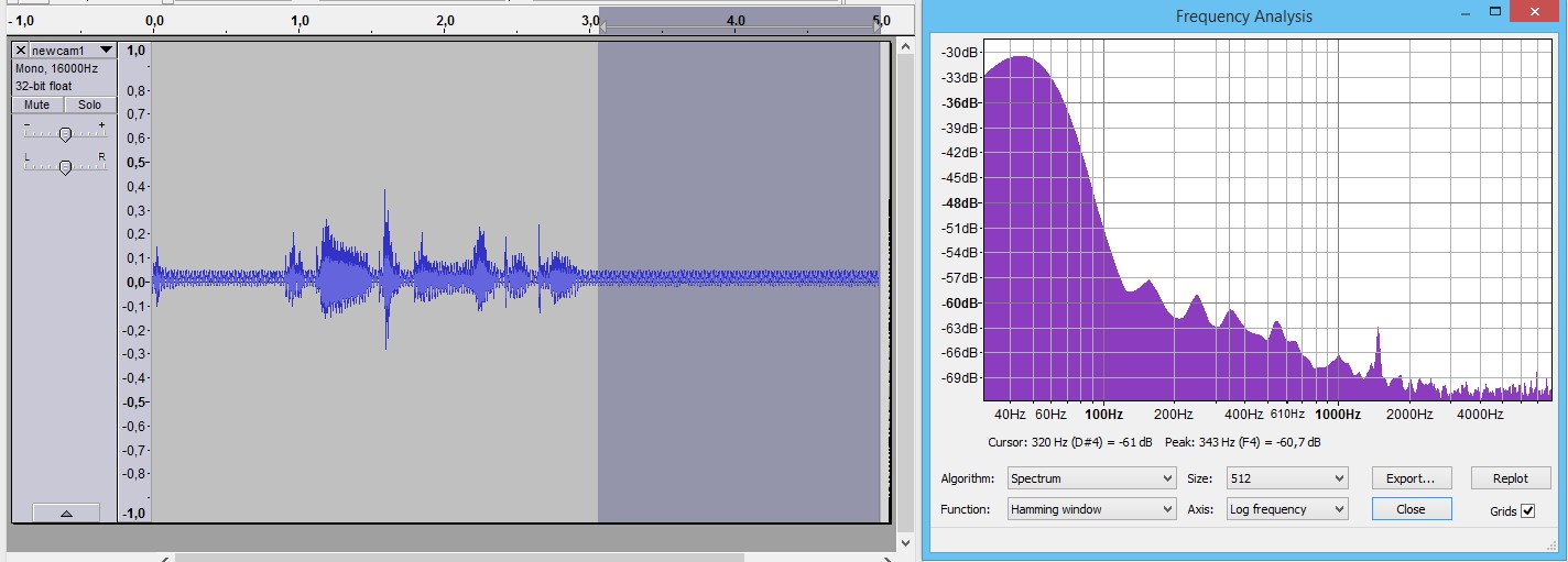
That is still pretty bad, but not quite as horrible as the first camera I tested. Besides, when the robot is moving the motors will make a lot of noise anyways, so I always had a plan to try to come up with some innovative noise suppression algorithms to preprocess the audio signal before letting Pocket Sphinx try to recognize speech from the signal. The positive thing about those new webcams is that they can actually record at 16 kHz, unlike my original webcam!
July 9th, 2015 - MPU6050 work, second package arrives
Interestingly, today the second package I ordered arrived as well, the one with the jumper wires, voltage converter and the stereo amplifier. However, I wanted to get my MPU6050 that I had soldered the pins to yesterday up and running, so I ignored the new package for now.
I started by studying how to use the I2C interface of the Raspberry Pi. Again I used my older Raspberry Pi as the test bench, in case I short something or otherwise make some serious mistakes connecting it. I first used the instructions I found here for enabling the I2C interface in the first place, and then followed some more specific documentation about how to interface the MPU6050 module with the Raspberry Pi.
The connection is basically pretty easy, like this:
    - Pin 1 - 3.3V connect to VCC
    - Pin 3 - SDA connect to SDA
    - Pin 5 - SCL connect to SCL
    - Pin 6 - Ground connect to GND
After making the connections I tested it with the i2cdetect utility, and it showed that
the I2C address 0x68 had a device connected! Great!
July 8th, 2015 - The first package from China arrives, Piro chassis work
Today I got the first package from China delivered! Interestingly, it was not the first package I ordered, nor even the second, but the third package with the 10 pieces of the L7805 voltage regulators and the MPU6050 gyro. The gyro did not have the pins soldered to the board, so the first step was to solder them in. It had been years since I last soldered anything, and even then it had been basically just joining a couple of wires together, never anything as small as this. Besides, my eyesight is not what it used to be, so I was quite worried about this whole soldering endeavor.
I watched some YouTube soldering tutorials before starting, and those boosted my confidence enough that I managed to slowly and carefully get the pins soldered with actually less trouble than I had anticipated.
After getting the pins soldered, I decided to continue working on the chassis for my robot, which I had started a few days ago. I plan to use an old VHS cassette storage case made from ABS plastic as the front and back sides of the robot, with some aluminum sheet in the bottom where the motors will be connected to. I thought that aluminum sheet would also work nicely as the common signal ground for all the electronics devices, much like the chassis of a car.
July 7th, 2015 - Pocket Sphinx internals
During the past couple of days I have studied the source code of Pocket Sphinx, trying to learn how it works. I decided to first focus on the front end code of the speech recognition algorithm, that is, the code that takes the input WAV data and converts it to something that the actual speech recognition code uses. I found the sources for the FFT algorithm that it uses (FFT being about the only recognizable algorithm to me), and am trying to figure out all the code around that. I have been googling about Cepstrals, Hidden Markov Models, and other stuff related to speech recognition, and trying to understand the algorithms. I wanted to get an understanding of the "feature buffer" that the front end generates based on the input wave data, so I decided to generate a BMP file of that data, with each row showing one feature frame (100ms of wave data), and each column showing the data of one feature vector. Each row consists of 39 vectors (13 Cepstral values, 13 Cepstral Delta values, and 13 Cepstral Delta Delta values). The color of the pixel is green if the vector is negative, and blue if it is positive, with the brightness of the pixel indicating the absolute magnitude of the vector.


Here above are images from me speaking "Yes" on the left and "No" on the right. And what use did I then have for these images, you ask? Well, I haven't figured that part out yet, other than that they helped me understand how difficult it is to find some patterns from data like the above.
July 5th, 2015 - Motor controller purchased
Today I finally purchased the motor controller (H-bridge) for the motors. I went with an L298N Stepper Motor Driver Controller Board from DealExtreme, as I found a good use guide for that exact motor driver. It should be reasonably simple to interface with a Raspberry Pi. I also added a solderless breadboard and some breadboard jumper wires to my package, as many electronics tutorials use a breadboard for testing various electronics devices, and I have never had such a breadboard before.
July 4th, 2015 - Raspberry Pi camera arrives
Okay, the first package of the robot parts arrived today! It was the Pi Camera I ordered from the local electronics store. Boy, what a difference between the picture quality of this camera and that of the web camera I used in my earlier picture capture tests!
That image above is rotated and scaled down from the original 2592x1944 size. Even in the relatively low-light conditions it captures very clear images! I immediately began to look into implementing camera capture code into my piro project sources.
I found a good tutorial about using the Pi Camera together with OpenCV from here, with the actual source code at https://dl.dropboxusercontent.com/u/5042323/camcv_vidS16_09_13.cpp. I used that source code as a template for my own camera capture code in Piro.
July 3rd, 2015 - Motors ordered
Today I continued my study of the optimum motors to purchase, and while looking for information I found a very good blog post about a Raspberry Pi balancing robot. This blog had information about the motors used, which were 630 rpm at 6V with 0.79 kg-cm torque. That was higher speed than I was aiming at, but it was good to know that even the lower-end 0.79 kg-cm torque was enough to keep a balancing robot balanced. I looked at the specs from the DealExtreme options, and found these three best candidates:
- ZnDiy-BRY 12V DC 300RPM/6V DC 150RPM Powerful High Torque Gear Box Motor with a torque of 2 kg-cm
- ZnDiy-BRY DC 12V 400RPM / DC 6V 200RPM High Torque Gear Motor - Silver with a torque of 1.5 kg-cm
- ZnDiy-BRY DC 12V 500RPM / DC 6V 250RPM High Torque Gear Motor - Silver with a torque of 1 kg-cm
I decided to go with the middle option, the 400rpm model with 1.5 kg-cm torque, as the best compromise between rotational speed and torque. I ordered two of those with the total price of 17.30 EUR. Now I still need a motor controller to be able to control the speed and direction of the motors.
July 2nd, 2015 - Optimum motor gearing?
I have been pushing back purchasing the motors for my robot, as I have not been sure what gearing they should have. DealExtreme has a lot of different geared motors available with different gearing ratios, so today I finally decided to actually calculate the needed gearing.
If I want my robot to be able to move with a normal walking speed, plus some buffer to keep its balance, I decided to aim for a top speed of 10km/h. A nice round number. Converting for more usable units, 10 km/h = 10000 m/h = 2.8 m/s = 2800 mm/s. So, if I plan to have wheels with a 70 mm diameter, that would result in 219 mm/rotation = 12.7 rotations/s = 763 rpm. If instead I would have 120 mm diameter wheels, the result would be 377 mm/rotation = 7.42 rotations/s = 445 rpm. So, looks like of the possible options, a gearing of 600rpm at 12V (or 300 rpm at 6V) might be the best option. However, I also want the motors to have sufficient torque to handle balancing properly, and since the faster the gearing the smaller the torque, perhaps I don't need quite that high a speed. I could not yet make up my mind about what motors to order.
July 1st, 2015 - Audio input continues, Camera Module ordered
After I got the web camera microphone input working, I recorded some test audio, but the quality was pretty bad. It took me some time to debug my code to realize that the problem was not actually in my code, but instead enabling the webcam video side caused the audio recording to warble! That was pretty frustrating find, as that means my idea of using two webcams for stereo vision and audio source location will probably not work.
I decided to order the Raspberry Pi Camera Module, as that is supposed to give much better picture quality and also take much less CPU resources (and USB bandwidth) to use. I looked online for places to purchase it, decided to go with a local online electronics store www.piirilevyt.fi where the NoIR Camera Module cost 30.00 EUR. I should be able to use the webcams I ordered from China as microphones in any case, and since they will look like cameras they will look like the eyes of the robot even if I use the Pi Camera for the actual computer vision work.
I also studied how the ALSA amixer program works, and added code based on that to set the microphone volume level when my piro executable starts.
June 30th, 2015 - Audio input
Today I started working on the audio input (recording) code for my robot. I found a good source from the picam project at https://github.com/iizukanao/picam/blob/master/stream.c. Since I am using the same thread for both audio input and audio output, I will need to make sure neither the audio input nor output run out of buffer space. This is a little bit tricky, but luckily the SVOX Pico pico_getData() API call is designed so that it only takes at most 200ms and is meant to be called repeatedly until all the speech wave data has been created.
June 29th, 2015 - Piro software project started!
Today I started working on the code that will run in my Piro robot. I started with implementing the SVOX Pico client into my project. This was pretty easy after I found and downloaded the http://dafpolo.free.fr/telecharger/svoxpico/SVOX_Pico_Manual.pdf and used the examples and API reference provided in that manual. I copied the audio output technique I had used in rpix86 and just changed the actual wave data generation to call SVOX Pico instead of my SoundBlaster emulation code. After some adjustments I was able the make my code speak whatever text I told it to say. Pretty neat!
After I got speech output working, I decided to also try to implement web camera capture inside my own project. I used the source code of fswebcam from https://github.com/fsphil/fswebcam/blob/master/fswebcam.c as a source, and implemented my own version of that code. I plan to run audio in one thread, video capture in another thread, and balancing and high level artificial intelligence code in a third thread. That leaves still one concurrent thread available in the quad-core Raspberry Pi 2 for some additional stuff I may decide to implement.
June 28th, 2015 - Another package ordered, OpenCV installation
After I had ordered the package yesterday, I realized that I made some mistakes with it. First, according to various balancing robot tutorials I found, I will need both a gyro and an accelerometer. The part I ordered was only an accelerometer, so I still needed a gyro. Also, I decided that I want to use separate power sources for the different components of my robot:
- Full 11V for the motors
- One 5V voltage converter for the Raspberry Pi
- One 5V voltage converter for the 2x3W stereo amplifier
- One 5V voltage converter for the servos that turn the head of the robot
- L7805CV 5V Voltage Regulator ICs (10 PCS) (3.56 EUR)
- GY-521 MPU6050 3-Axis Acceleration Gyroscope 6DOF Module - Blue (2.91 EUR)
I also installed the famous OpenCV Computer Vision software on my Raspberry Pi. I installed the latest version 3.0 of the package, using the installation instructions found here. The installation basically consisted of the following simple steps, but the actual compilation part took over an hour even when running it with three threads on the Raspberry Pi 2:
    $ mkdir build
    $ cd build
    $ cmake ..
    $ make -j3
    $ sudo make install
June 27th, 2015 - Ordered more stuff, installed SVOX Pico, laptop battery stuff
Today I ordered the first package of electronics stuff I will need for my robot.
- Single Port Female to Female Jumper Wire Set (50-Pack/20CM-Length) (3.45 EUR)
- HC-SR04 Ultrasonic Sensor Distance Measuring Module (1.98 EUR)
- ADXL345 Digital 3-Axis Gravity Acceleration Sensor Module - Blue (2.62 EUR)
- PAM8403 DC 5V Class D Mini Digital Amplifier Board Module - Green (1.34 EUR)
- LM2596 3A DC to DC Adjustable Step-down Voltage Regulator Buck Converter Module - Green (1.97 EUR)
I also installed SVOX Pico text-to-speech system. I tested a couple of other text-to-speech products as well (espeak and flite), but I did not like how those sounded. SVOX Pico sounds pretty much like the female voice of a navigator device, so I decided that would fit my robot perfectly. Looks like it will be a female robot, then. :) I used the installation instructions from here, with some additional installation instructions here. To test the engine after installation, use a command like
$ pico2wave -w test.wav "it works."
The 2-channel 3-watt amplifier I purchased will be used to amplify the Raspberry Pi headphone
connector signal for the speakers I got from an old broken down Acer laptop. Those are small 2 watt
speakers, but they are enclosed (with some weird shapes) and seem to have a reasonable audio quality
for their size.
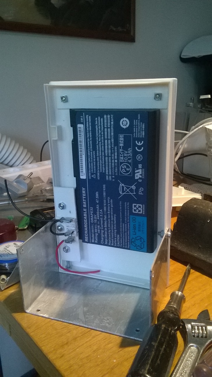
Another part of the broken down laptop I would like to use is the battery. The battery of the laptop seems to be fine, it is just the motherboard that is broken, so I googled for information about the possibility of using a laptop battery for other projects. I found this blog post about it. Even though my laptop has a different battery with a different connector (mine is a GRAPE32 10.8V 4400mAh 47.5Wh battery with a 7-pin connector), this blog post seemed to provide a lot of good information. By using a voltmeter with the laptop motherboard I was able to determine which was the "switch" connector that needs to be connected to ground for the battery to activate. Here is a super cool ASCII art picture of the pins:
            |                                   |
            |     |     |     |     |     |     |
  +---------+-----+-----+-----+-----+-----+-----+-----------------------------------------------------
  |         |           |                       |
  |         + +11v      + Switch .............. + GND
I also found a lot of good general information about laptop batteries
here.
I plan to use the original laptop as a charging station (as that part of it still works fine), so I just need to either build or purchase a suitable connector into my robot. The battery connector seems to be of the BA07EM type, but I have not found a site that would sell a single one of such a connector, so I will probably need to make one myself. A 3D printer might be useful for such, sadly I don't have one (as I haven't had a need for one until now). And purchasing a 3D printer just for a robot that I aim to make as cheaply as possibly somewhat defeats the whole idea.
June 26th, 2015 - aplay/arecord troubleshooting, Pocket Sphinx install
Seems like playing audio from my Raspberry Pi stopped working after I installed the webcam. After some googling I found a good audio troubleshooting guide which helped me to get audio working again. Installing a webcam changes the hardware audio device IDs, so that the default device became the webcam instead of the headphone audio out.
For reference, here are the commands to record audio from a webcam, and to play it back (after using the above guide to make sure aplay plays audio via the correct device). The arecord parameters are: format = signed 16bit little-endian, rate = 22050, device = hardware 0,0, duration = 5 seconds, output file.
    $ arecord -f S16_LE -r 22050 -D hw:0,0 -d 5 test3.wav
    $ aplay test3.wav
After I got the audio working again, I installed Pocket Sphinx speech recognition system (or speech-to-text system). I found the best guide for installing it on the Raspberry Pi from the Jasper project documentation. I did not plan to install the whole Jasper system, so I just took the relevant parts from the installation document concerning the Pocket Sphinx installation. I recorded some voice commands and tested the speech-to-text features with a command like
$ pocketsphinx_continuous -infile test2-16k.wav
I found out that my webcam cannot record at 16 kHz which the Pocket Sphinx needs, it records at 11 kHz when told to record at 16 kHz. After upsampling the resulting 11kHz file to 16 kHz, the speech recognition result was pretty nonsensical. I said "testing, testing, one, two, three", and the text result was "russia, russia, I dude". :) It seems that upsampling is out of the question when doing speech recognition.
There are a ton of parameters and options for Pocket Sphinx, so getting to understand what they all mean (and how the system works in general) will take quite a lot of time. But since the webcams I ordered will take a couple of weeks to arrive, I will have a lot of time to study it before I can even start building my robot.
June 25th, 2015 - Installing a webcam
I will need a camera in my robot to be able to program Computer Vision features into it. I have an old Philips PC750K webcam that is not supported by the newer Windows versions (I think it was last supported by Windows XP, anything newer fails to work with it), so I thought I could use it in my robot instead. I found instructions about using a webcam in Raspberry Pi here, and pretty quickly I was able to take pictures using the webcam. The command to take a picture is:
$ fswebcam -r 640x480 -d /dev/video0 image.jpg
The picture quality is pretty bad, but perhaps it would be enough to get me started on
face detection algorithms, for example.

My plan was to put two webcams in my robot and then use Computer Stereo Vision to map the environment the robot currently is. Using two webcams with microphones also hopefully allows me to detect the direction of sounds, so that the robot could turn to face people who are talking to it. Thus, I ordered three small cheap webcams from DealExtreme for this purpose. I got three just in case I break one, and because getting three items upgraded my package to a faster mailing method. The total price was still below 20 EUR (the tax-free limit for stuff ordered outside of EU).
June 24th, 2015 - Testing my old Futaba servos from 1980
This was the first step in my robot project. I wanted to test whether the four old Futaba
servos I had got as a Christmas present back in 1980 still worked. I connected them to my
older Raspberry Pi (just in case they would somehow destroy my Pi, I did not want to
sacrifice my new Raspberry Pi 2 yet), and used ServoBlaster
to send the PWM signals to the GPIO port to set the servo angle. Somewhat to my surprise
those old servos (which I have not used for at least 30 years) still worked fine!
I also had to look up the connector pinout from Google, turned out those old connectors are "Futaba type G" connectors, with a pinout of white (control) being the separate pin and then red (5V) and black (ground). I happened to have a short 4-wire female-to-female connector cable that I was able to use in these tests.